Control Delock KVM with pikvm (infra red)
Background
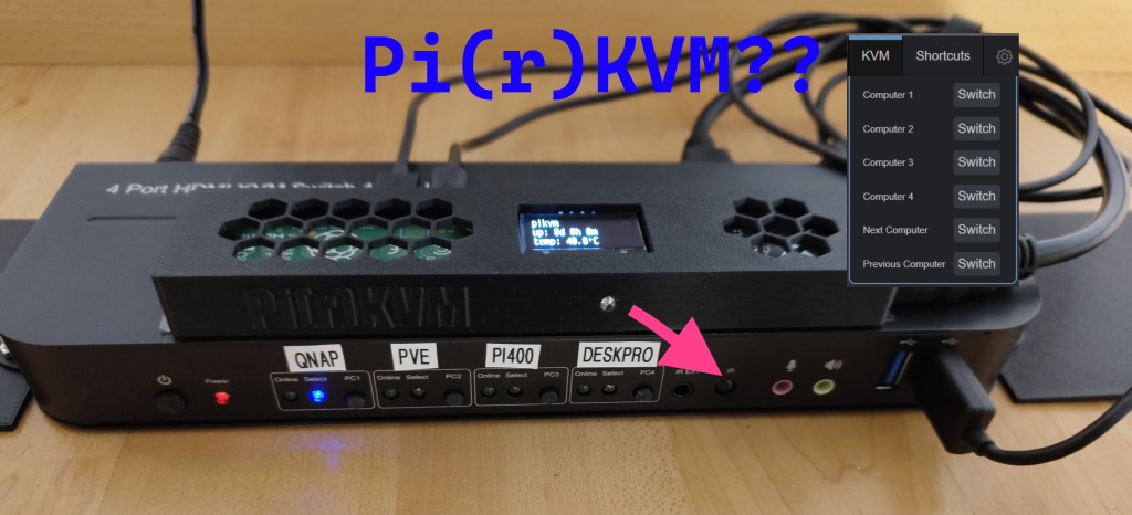
I heard of pikvm for a while now. Never got around to buy or make one. Until now 😎. As I had a Raspberry Pi Zero 2 laying around, all I needed was a few cables, an sd card, an IR LED and a CSI to HDMI adapter, to make this work. I wasn’t happy with controlling just one machine, so I decided to order another Delock KVM 4 Port HDMI. I have been very satisfied with the display port variant of it.
A few highlights of the Delock KVM DP for me are:
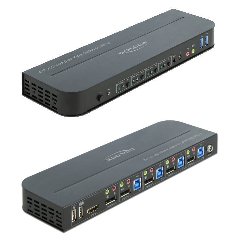
- reasonable price ~140$
- MST Multi-Stream Transport (I don’t use yet)
- high refresh rate (my main monitor runs 3440x1440 @ 120HZ)
- infrared remote control
- Hotkey works with the wireless dongle of my G915 Logitech keyboard
- slim design
The HDMI Version that I used for my project, pi(r)kvm 🤔, is pretty much the same. Comes with the same IR remote, that even has the same IR codes.
The goal
The main 🎯 is to have a switchable multi port network kvm. As simple as that.
Parts list
- Delock KVM Switch (it should work with any IR based KVMs, as long as you know the IR codes)
- Raspberry Zero 2 W (This guide is based on the Zero 2, you’d have to adopt for a PI 4b for yourself)
- HDMI to CSI adapter e.g. https://www.waveshare.com/wiki/HDMI_to_CSI_Adapter
- Flexible flat cable / circuit (22pin to 15pin) was not included for me with the waveshare CSI adapter
- SD card
- 2x Micro USB cables
- 1x Short HDMI cable
- IR LED (I de-soldered one from a cheap led strip remote control)
- a few wires
- Cables for the KVM, USB and HDMI
Optional
- 3D Printer for a case
- Mini OLED display
Hardware assembly
The assembly is pretty straight forward. 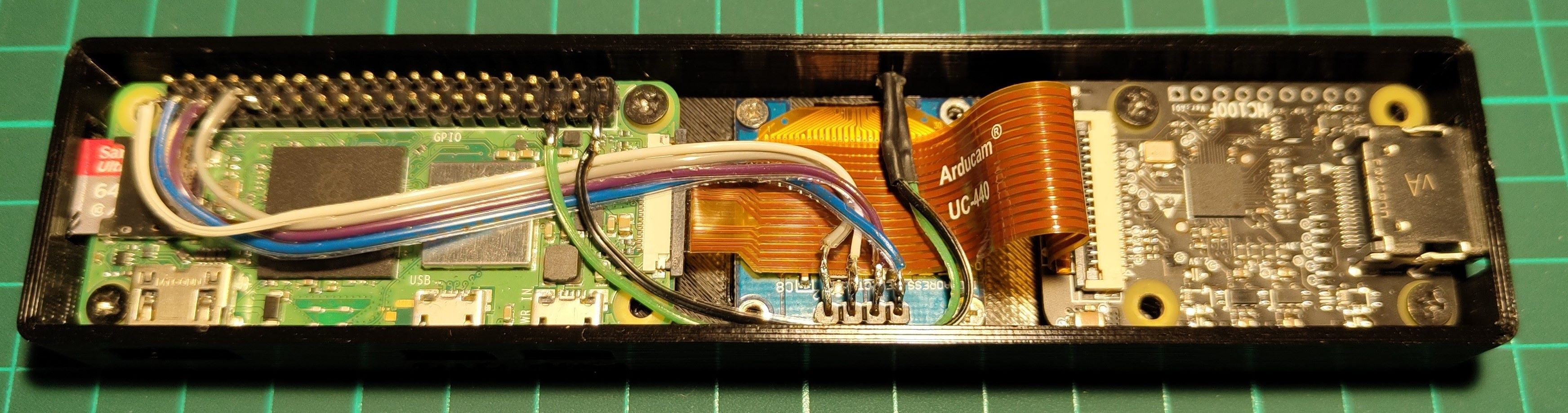 assembled pi zero (crappy soldering)
- Connect the Pi Zero 2 with the HDMI to CSI-2 cable to the HDMI to CSI Adapter
- Solder wires to the IR-LED, connect + anode to the GPIO 19 (PIN35) and the - cathode to GND (PIN39) of the Pi Zero 21
- Follow the guide to connect the OLED here: https://github.com/pikvm/pikvm/issues/797
- Connect HDMI Cable (Delock HDMI out to HDMI Adapter IN)
- Connect Pi Zero Power to the KVMs Keyboard with a micro usb cable.2
- Connect Pi Zero 2nd USB (OTG) to the Front USB 3.0 with a micro usb cable.2
Software
Prepare the SD Card for first boot
- Burn the Zero 2 W image from https://pikvm.org/download/
- add
dtoverlay=gpio-ir-tx,gpio_pin=19toconfig.txt, https://pinout.xyz/pinout/pin35_gpio19 - add your WIFI creds to
pikvm.txtsee details here: https://docs.pikvm.org/first_steps/#first-power-on - boot your pi and follow https://docs.pikvm.org/first_steps
Add IR Commands to web interface
enter a shell session (ssh or web interface terminal)
Check the IR LED
- check if you have
/dev/lirc0device - test the IR LED, sending a test code (next computer)
sudo ir-ctl -S nec:0xe916 -d /dev/lirc0use your phone camera to see if the IR LED blinks. If it does, point the IR LED at the IR Receiver LED of the Delock KVM. Rerun the command, you should hear a beep and the input on the Delock KVM should switch to the next computer.
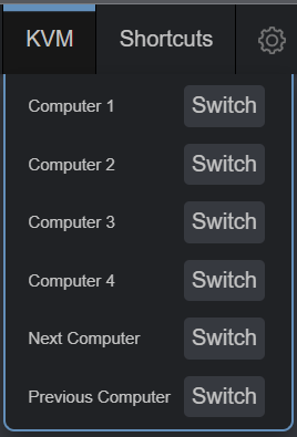
Modify to web interface
- make sure you change read/write mode with
rw - following the guidelines here https://docs.pikvm.org/gpio/#cmd
- add
kvmd ALL=(ALL) NOPASSWD: /usr/bin/ir-ctlto/etc/sudoers.d/custom_commands(sudo nano /etc/sudoers.d/custom_commands`) to allow the web interface to use ir-ctl - add the lines below to
/etc/kvmd/override.yaml
1
2
3
4
5
6
7
8
9
10
11
12
13
14
15
16
17
18
19
20
21
22
23
24
25
26
27
28
29
30
31
32
33
34
35
36
37
38
39
40
41
42
43
44
45
46
47
48
49
50
51
52
53
54
55
56
57
58
59
60
61
62
kvmd:
    gpio:
        drivers:
            computer_1:
                type: cmd
                cmd: [/usr/bin/sudo, ir-ctl, -S, nec:0xf708, -d, /dev/lirc0]
            computer_2:
                type: cmd
                cmd: [/usr/bin/sudo, ir-ctl, -S, nec:0xf50a, -d, /dev/lirc0]
            computer_3:
                type: cmd
                cmd: [/usr/bin/sudo, ir-ctl, -S, nec:0xf30c, -d, /dev/lirc0]
            computer_4:
                type: cmd
                cmd: [/usr/bin/sudo, ir-ctl, -S, nec:0xf10e, -d, /dev/lirc0]
            next_computer:
                type: cmd
                cmd: [/usr/bin/sudo, ir-ctl, -S, nec:0xe916, -d, /dev/lirc0]
            previous_computer:
                type: cmd
                cmd: [/usr/bin/sudo, ir-ctl, -S, nec:0xeb14, -d, /dev/lirc0]
        scheme:
            computer_1_button:
                driver: computer_1
                pin: 0
                mode: output
                switch: false
            computer_2_button:
                driver: computer_2
                pin: 0
                mode: output
                switch: false
            computer_3_button:
                driver: computer_3
                pin: 0
                mode: output
                switch: false
            computer_4_button:
                driver: computer_4
                pin: 0
                mode: output
                switch: false
            next_computer_button:
                driver: next_computer
                pin: 0
                mode: output
                switch: false
            previous_computer_button:
                driver: previous_computer
                pin: 0
                mode: output
                switch: false
        view:
            header:
                title: KVM
            table:
                - ["#Computer 1", "computer_1_button|Switch"]
                - ["#Computer 2", "computer_2_button|Switch"]
                - ["#Computer 3", "computer_3_button|Switch"]
                - ["#Computer 4", "computer_4_button|Switch"]
                - ["#Next Computer", "next_computer_button|Switch"]
                - ["#Previous Computer", "previous_computer_button|Switch"]
once changed, run sudo systemctl restart kvmd to reload
🥳🎉🥳🎉 That should be it, check out the web interface. 🥳🎉🥳🎉
Thanks to these people
👏👏👏 please consider donating them
- pikvm
- NovaspiritTech
- crutonjohn the people in this thread here: https://github.com/crutonjohn/pikvm-ir/issues/5
- https://www.thingiverse.com/thing:4915627
3D printable cases
I have designed a two cases. Use them as an inspiration. It works for my needs. I have stacked the case above the kvm and it fits almost exactly in my rack using 1 U.
without OLED
Kvm_Case_Body.png) body body | Kvm_Case_Body_inside.png) inside inside | Kvm_Case_Body_back.png) back back |
with OLED
Kvm_Case_Body_Oled.png) Body Body | Kvm_Case_Body_Oled_inside.png) inside inside | Kvm_Case_Body_Oled_back.png) back back |
Notes
The IR LED might need a current limiting resistor. (Inputs on as to why, how to connect and the size of the resistor would be appreciated) ↩︎
Connect PWR to KEYB, for constant powering the Pi. Connecting OTG to KEYB has two drawbacks, switching to a not connected input on the KVM would result in power loss of the Pi and the hotkey [SCRLK] doesn’t work with the Delock KVM anyways. IR Switching FTW 🏆. ↩︎ ↩︎2